| Home | Energy | Nuclear | Electricity | Climate Change | Lighting Control | Contacts | Links |
|---|
INTRODUCTION:
The FNR discharge temperature setpoint is adjusted by changing the FNR core zone geometry, which is done by adjusting the depth of insertion of the movable fuel tube bundles into the matrix of fixed fuel tube bundles. When the reactor is under constant thermal load the insertion depth of each movable fuel bundle should be trimmed to achieve a uniform movable fuel bundle liquid sodium discharge temperature.
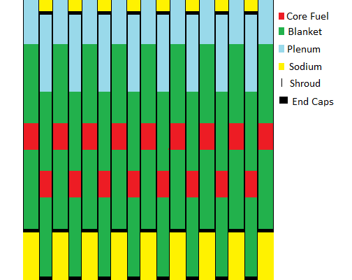
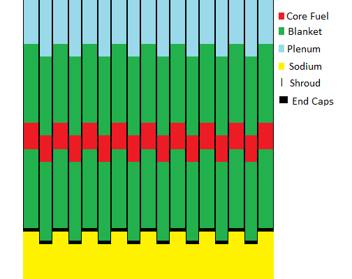
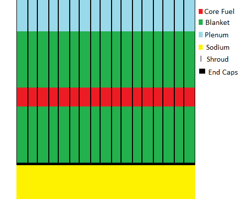
The following diagrams show a row of 9 fixed fuel tube bundles separated by 8 slightly narrower movable fuel tube bundles. The movable fuel tube bundles are inserted into the bottom of the matrix of fixed fuel tube bundles. On these diagrams the shrouds separating the fixed and movable fuel tube bundles appear as thin black lines, core fuel portions of the fuel bundles are shown in red, the blanket portions of the fuel bundles are shown in green, the plenum portions of the fuel bundles are shown in light blue and the fuel tube end caps appear as solid black.
When the reactor is in cold shutdown the lower ends of the movable fuel tubes are 1.08 m below the lower ends of the fixed fuel tubes. As shown on the following diagram when the reactor is in cold shutdown the core fuel portions of the fixed and movable fuel bundles are well separated and are isolated from each other by neutron absorbing U-238 in the blanket fuel, shown in green, which keep the reactor sub-critical.

Sufficient further insertion of the movable fuel bundles into the matrix of fixed fuel bundles causes the core rods in the movable fuel bundles to partially overlap the core rods in the fixed fuel bundles. When the reactor has new core fuel (average 20% Pu, no fission products) that partial core rod overlap causes the reactor to become critical. Once critical further insertion of the movable fuel bundles into the matrix of fixed fuel bundles raises the reactor operating temperature setpoint.
The following diagram shows the relative positions of the fixed and movable fuel tube bundles when the reactor is operating and the fuel is new (or has recently been reprocessed).

As the fuel ages the average plutonium concentration in the reactor core fuel rods gradually decreases and the fission product concentration in the reactor core fuel rods gradually rises. To compensate for this fuel aging mechanism from time to time the movable fuel bundles are slightly further inserted into the fixed fuel bundle matrix to maintain the desired primary liquid sodium surface temperature setpoint. This further insertion of the movable fuel bundles also reduces the fraction of fission neutrons which diffuse out of the reactor core zone and are absorbed in the upper and lower blanket zones. When the reactor fuel has aged to the point that it is due for reprocessing the average plutonium concentration in the core fuel has dropped to about 12.7% Pu and the core fuel portion of the movable fuel bundles fully overlaps the core fuel portions of the fixed fuel bundles as shown in the following diagram. In this state the movable fuel bundles are fully inserted into the matrix of fixed fuel bundles. When the core fuel requires reprocessing the primary liquid sodium surface temperature will fall below its design value in spite of full insertion of the movable fuel bundles into the matrix of fixed fuel bundles.

Note that in the reactor core zone each fuel tube contains one core fuel rod. When the fuel is new the movable fuel bundles should overlap the fixed fuel bundles by slightly more than one half core fuel rod length. When the fuel is old the movable fuel bundles should overlap the fixed fuel bundles by one core rod length. This fuel bundle overlap relationship ensures a decrease in reactor reactivity during fuel disassembly resulting from prompt neutron criticality. Note that during fuel disassembly only the core fuel rods in the fixed fuel bundles will move toward the plenum. This fuel rod movement must decrease, not increase, the reactor reactivity.
FUEL MECHANICAL STABILITY:
A FNR ususally operates at the threshold of criticality. It is essential for the fuel geometry to remain mechanically stable to avoid reactivity surges related to uncontrolled fluctuations in fuel geometry caused by an imperfect mechanical control system which will have some position error due to hysterisis and other mechanical issues. The requirement for fuel geometric stability leads to a fuel bundle arrangement consisting of two fuel bundle sizes that provides horizontal as well as vertical fuel assembly mechanical stability.
REACTIVITY ISSUE:
If two partially overlapping parallel rods are each suspended from the ends far from the overlap and then heated the overlap will increase with increasing temperature. We need a mechanical arrangement where the overlap decreases with increasing temperature. Hence the core rods must both be supported by their hot ends. This is easy for the core rods of the fixed fuel bundles.
There is a fundamental issue that the core fuel rods of the movable fuel bundles need to be suspended from their hot ends so that the reactor reactivity decreases with increasing fuel rod temperature.
One possible solution is for the weight of each such fuel rod and the blanket rods above it to be born by a central quartz rod that is coaxial with the fuel rod. This arrangement requires a central hole througn the core fuel rod. At the top end (cool end) of this central hole through the core fuel rod yhe hole is blocked so that in effect the quartz rod supports both the core fuel rod and the blanket rods above it. As the core fuel rod thermally expands its bottom end slides down the quartz rod.
A more robust mechanical solution to this problem is being sought.
ORDER OF ASSEMBLY:
Note that movable FNR fuel bundles are always added to the assembly of fuel bundles in the fully retracted position BEFORE adjacent fixed fuel bundles are added and are always removed AFTER adjacent fixed fuel bundles are removed so that during fuel bundle addition or removal a movable fuel bundle is NEVER passed through an assembled fixed fuel bundle matrix.
THERMAL POWER CONTROL:
In a liquid sodium cooled FNR the primary means of thermal power control is fuel thermal expansion and contraction which changes the FNR reactivity. As the primary liquid sodium coolant temperature rises to the reactor temperature setpoint fuel thermal expansion causes the core zone reactivity to drop below zero, which shuts down the chain reaction. Note that as the reactor thermal load decreases part of the core fuel temperature increases which shuts down the chain reaction. In effect the FNR maintains a constant average fuel temperature. As the thermal load increases part of the core fuel centerline temperature will decrease while the temperature drop between the core fuel center line and the liquid sodium increases.
CORE ZONE:
The core zone is the region where core fuel rods in fixed fuel bundles overlap core fuel rods in movable fuel bundles.
[Core zone thickness]
= [0.60 m - (Distance movable fuel bundles are withdrawn)]
Thus the core zone thickness is adjustable from 0 m to 0.6 m. However, to obtain reactor criticality when the core fuel average Pu fraction is 20% the minimum overlap length between the movable fuel bundle core fuel and the fixed fuel bundle core fuel should be about 0.35 m.
In the reactor on state the bulk reaqctivity in the core zone is greater than zero. The rate of neutron production in the core zone precisely equals to the rate of neutron absorption in the core zone plus the rate of neutron diffusion out of the core zone into the adjacent upper and lower blanket zones.
In practice during reactor turn-on externally supplied heat is used to melt the sodium and then the core zone thickness is gradually increased until the reactor becomes critical. The liquid sodium temperature will then rise until the reactor becomes subcritical. Then the core zone thickness is again slightly increased until again the liquid sodium temperature rises sufficiently to make the reactor subcritical. This procedure is repeated over and over again until the liquid sodium temperature reaches the desired value of 460 degrees C. If the reactor design is correct the desired liquid sodium operating temperature will be reached when the core zone thickness is about 0.35 m and the average Pu weight fraction in the core fuel rods is 20%.
As the core fuel ages, to maintain the desired liquid sodium operating temperature, the core zone thickness must be gradually increased to ultimately become 0.60 m when the Pu weight fraction in the core fuel has fallen to about 12.7%.
UPPER AND LOWER BLANKET MINIMUM THICKNESS:
the nomional [Upper and lower blanket thickness]
= [1.8 m]
OPTIMUM REACTOR MODULATION:
The optimum reactor modulation will occur when the average fissile concentration in the upper blanket equals the average fissile concentration in the lower blanket.
As shown on the web page titled: FNR FUEL RODS the initial Pu weight fraction in the movable core rods should be 24.______% and the average Pu weight fraction in the fixed core rods should be 16.______%.
When the core fuel is due for reprocessing the average Pu weight fraction in the core fuel will be about 12.7%. We must examine the reactor material distribution to determine if the core zone will remain critical at this average Pu fraction in the core rods.
MULTIPLE INDEPENDENT SHUTDOWN MECHANISMS:
If all of the fuel bundles are initially at their normal operating state and then one half of the movable fuel bundles are withdrawn the reactor will reliably shut down. This safety shutdown condition enables two fully independent reactor cold shutdown mechanisms. In the normal operating state the core fuel is in two partially displaced layers. In the shutdown state the core fuel is in two widely displaced layers.
REACTOR OFF:
When the reactor is off the movable fuel bundles are 1.08 m withdrawn.
In the reactor off state:
Middle core zone thickness
= 0.6 m - 1.08 m
= - 0.48 m
In the reactor off state there must be absolute certainty that the chain reaction will stop regardless of the liquid sodium temperature.
The fuel bundles are engineered such that with the movable fuel bundles 1.08 m withdrawn the entire reactor is sub-critical. Ideally if a single active fuel bundle in an array of active fuel bundles with movable portions withdrawn is fully inserted the reactor should remain subcritical. This feature is desirable to prevent problems if a single fuel bundle should somehow jam in its fully inserted position.
In the reactor off state the fissile fuel density in the upper and lower blanket zones is the same as in the reactor on state. Hence this fissile fuel density must cause the reactor to be subcritical.
In the reactor cold shutdown state there is no core zone.
SUMMARY:
Proper reactor operation is dependent on initial correct fuel rod Pu weight fractions.
REACTOR MATHEMATICAL MODELLING:
We must solve the diffusion equation to find the diffusion fluxes of neutrons from the core region into the adjacent upper and lower blanket regions. These mathematical solutions are presented at:
FNR CORE and at FNR BLANKET.
PLUTONIUM DOUBLING TIME:
An issue of great importance in large scale deployment of FNRs is the FNR run time required for one FNR to breed enough surplus Pu-239 to allow startup of another identical FNR. This time may be calculated using the approximation that each plutonium atom fission releases of 3.1 neutrons of which 2.5 neutrons are required for sustaining long term reactor operation leaving 0.6 neutrons for breeding extra Pu-239. Thus fission of one atom of Pu-239 forms 0.6 atoms of extra Pu-239 in addition to the Pu-239 breeding that is required to sustain the nuclear reaction.
In one reactor cycle time 15% of the fuel weight fissions, which is 3 / 4 of the initial plutonium weight.
Thus in one reactor cycle time the fractional increase in Pu is:
0.6 (3 / 4) = 0.45
Thus the plutonium doubling time is:
(1 cycle time) / 0.45
= 2.22 cycle times
If one cycle time = 30 years then:
Pu doubling time = 2.22 (30 years)
= 66.67 years
This is the time required for one FNR to form enough excess Pu to enable starting another similar size FNR. Clearly this doubling time is too long to enable rapid deployment of FNRs using Pu obtained from FNR breeding. In the near term the number of operating FNRs will be limited by the availability of FNR core fuel for reactor startup.
With large scale implementation of FNRs the available supply of plutonium and trans-uranium actinides will soon be exhausted. Hence the issue of the Pu-239 doubling time physically constrains the rate of growth of the FNR fleet.
Thus FNRs are viable for disposing of transuranium actinides but due to the Pu-239 doubling time will not in the near future by themselves provide enough thermal power capacity for complete displacement of fossil fuels.
FNR DESIGN CONSISTENCY:
An issue that remains to be demonstrated is whether the present FNR mechanical design will meet the design target of reactor criticality at an ave